Custom Car Controller
Team size: 1 member
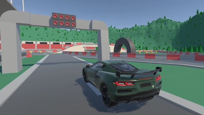
Custom Car Controller is a controller that I am making as an end-of-studies project.
The goal of the project is to make a controller that I will be able to use to make racing games.
Custom Car Controller
Team size: 1 member
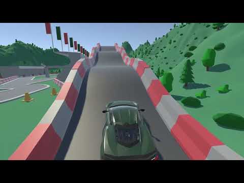
Custom Car Controller is a controller that I am making as an end-of-studies project.
The goal of the project is to make a controller that I will be able to use to make racing games.
What I did on this project:
The first step when making my controller was to create a custom wheel collider that will be in charge of almost everything in the controller.
The wheel collider is the element that makes the car roll, turn, and take bumps.
The wheel controller is split into 3 big parts:
- Suspension (Up force)
- Acceleration/Braking (Longitudinal force)
- Turning (Lateral force)
Suspension Force:
To make the suspension work, I am using a raycast that shoots to the ground from the top of the suspension to see if the wheel touches the ground and at what distance it is. This allows me then to calculate the force that the suspension applies to the wheel, and so the opposite force that is applied to the car's rigidbody at the position of the wheel.

Acceleration/Braking Force:
For now, the wheel recieves a certain torque from the car (via the engine/gearbox) and converts it to a forward force depending on its radius. This system will change later to introduce grip management.
For braking, the wheel recieves the percentage of brake the user applied, which it converts with the max brake torque. This gives a force that is then applied to the opposite side of the current wheel torque (so we can brake when going forward and backward).

Turning Force:
To calculate the turning force, a dot product between the wheel's right vector and the velocity of the wheel gives us the direction from which the wheel is currently taking force. By inverting this direction, we have the resistance force the wheel applies to the ground. Currently, I apply a multiplier to that force to imitate grip, but this will be changed in the future to add a more realistic grip behavior (using Pacejka's magic formula).

To simulate realistic vehicle movement, I implemented a custom powertrain system that links the engine to the driven wheels.
The engine RPM is first used to evaluate the engine torque using a predefined torque curve. This torque is then converted into wheel torque by applying the transmission gear ratio and differential ratio.
The computed wheel torque is transmitted to the wheel controllers, where it is used to calculate traction forces and vehicle acceleration.
Drivetrain Coupling Strategy
To determine engine RPM, I derived it from the driven wheels’ RPM.
This creates a rigid drivetrain constraint model where the engine and wheels are kinematically linked.

I started with this approach to stabilize the simulation and validate force interactions across the entire vehicle system (traction, suspension, weight transfer, and drag). Introducing a fully decoupled clutch model early would have added nonlinear torque feedback and additional tuning complexity, potentially slowing iteration on higher-priority systems such as tire forces and suspension response.
This rigid coupling provides numerical stability, predictable behavior, and efficient computation while remaining physically coherent for the intended gameplay scope.
The drivetrain abstraction was implemented in a modular way, allowing it to later be upgraded to a fully torque-based clutch coupling model without refactoring dependent systems. This future extension would enable advanced behaviors such as clutch slip, stall simulation, and more realistic gear transitions.
Resistive force
To simulate realistic speed limitation, I implemented aerodynamic drag using the classical drag equation.
Because aerodynamic drag increases with the square of velocity, the resistive force rises rapidly at high speeds.
This naturally produces an equilibrium point where propulsion force equals drag force, resulting in a physically emergent top speed without any artificial speed clamping.

This ensures the vehicle's maximum speed is determined by its power output and aerodynamic properties rather than hardcoded limits.
The first step when making my controller was to create a custom wheel collider that will be in charge of almost everything in the controller.
The wheel collider is the element that makes the car roll, turn, and take bumps.
The wheel controller is split into 3 big parts:
- Suspension (Up force)
- Acceleration/Braking (Longitudinal force)
- Turning (Lateral force)
Suspension Force:
To make the suspension work, I am using a raycast that shoots to the ground from the top of the suspension to see if the wheel touches the ground and at what distance it is. This allows me then to calculate the force that the suspension applies to the wheel, and so the opposite force that is applied to the car's rigidbody at the position of the wheel.
Acceleration/Braking Force:
For now, the wheel recieves a certain torque from the car (via the engine/gearbox) and converts it to a forward force depending on its radius. This system will change later to introduce grip management.
For braking, the wheel recieves the percentage of brake the user applied, which it converts with the max brake torque. This gives a force that is then applied to the opposite side of the current wheel torque (so we can brake when going forward and backward).
Turning Force:
To calculate the turning force, a dot product between the wheel's right vector and the velocity of the wheel gives us the direction from which the wheel is currently taking force. By inverting this direction, we have the resistance force the wheel applies to the ground. Currently, I apply a multiplier to that force to imitate grip, but this will be changed in the future to add a more realistic grip behavior (using Pacejka's magic formula).
To simulate realistic vehicle movement, I implemented a custom powertrain system that links the engine to the driven wheels.
The engine RPM is first used to evaluate the engine torque using a predefined torque curve. This torque is then converted into wheel torque by applying the transmission gear ratio and differential ratio.
The computed wheel torque is transmitted to the wheel controllers, where it is used to calculate traction forces and vehicle acceleration.
Drivetrain Coupling Strategy
To determine engine RPM, I derived it from the driven wheels’ RPM.
This creates a rigid drivetrain constraint model where the engine and wheels are kinematically linked.
I started with this approach to stabilize the simulation and validate force interactions across the entire vehicle system (traction, suspension, weight transfer, and drag). Introducing a fully decoupled clutch model early would have added nonlinear torque feedback and additional tuning complexity, potentially slowing iteration on higher-priority systems such as tire forces and suspension response.
This rigid coupling provides numerical stability, predictable behavior, and efficient computation while remaining physically coherent for the intended gameplay scope.
The drivetrain abstraction was implemented in a modular way, allowing it to later be upgraded to a fully torque-based clutch coupling model without refactoring dependent systems. This future extension would enable advanced behaviors such as clutch slip, stall simulation, and more realistic gear transitions.
Resistive force
To simulate realistic speed limitation, I implemented aerodynamic drag using the classical drag equation.
Because aerodynamic drag increases with the square of velocity, the resistive force rises rapidly at high speeds.
This naturally produces an equilibrium point where propulsion force equals drag force, resulting in a physically emergent top speed without any artificial speed clamping.
This ensures the vehicle's maximum speed is determined by its power output and aerodynamic properties rather than hardcoded limits.
Assets attribution:
- Car: Arno BARBÉ - Portfolio
- Environment: Kenney assets - CC0 license